• Hello there guest and Welcome to Modular Fox Mustangs home of the 2V, 3V, 4V, Coyote Modular Mustang Conversion Information Website!
    To gain full access you must Register. Registration is free and it takes only a few moments to complete.
    Already a member? Login here then!

Wiring expertise needed for Mod swap into 93 Town Car using OBD2

Zack

New Member
Hey guys, good to be here.
Im swapping a 4V/Whipple 2.9 into my 93 Lincoln Town Car.
Im using a Marauder harness, OBD2 and plan on using a Tablet with Wireless dashboard software for the gauges.

Essentially, I just need the engine to start and operate the fan. The rest of the car will retain the factory wiring.

I have removed the OBD2 wiring from a Marauder dash harness.

Here are my questions:
-How and where do I incorporate the PCM diode?
-What wires need to be HOT so the car will start using the Factory ignition switch?
(I have SCT software to turn PATS off)
-The OBD2 port has wiring for an ISO bus (what the hell is that and what does it get hooked up to?)
-The SCP Bus goes to various sensors....can I just hook the wires to the appropriate PCM inputs and be ok?

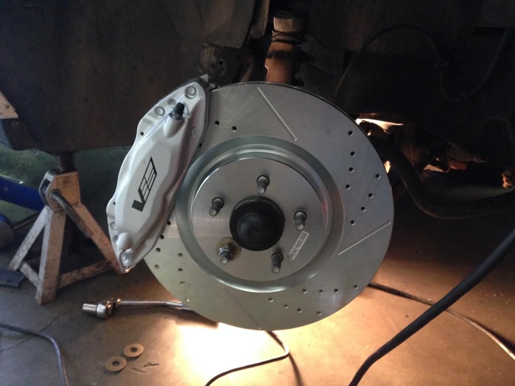
Ive attached a few pics, as well as the Marauder pcm pinout
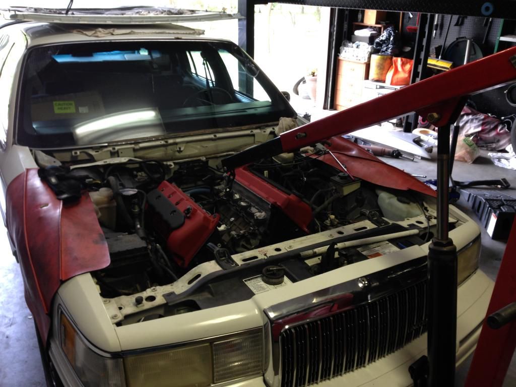


Zack

New Member
I have the donor harnesses all apart. What a daunting sight.
Any help would be much appreciated!!
And I'm using an auto trans, which makes this even more difficult
 

FuturaGuy

Well-Known Member
Staff member
Your post has been here for about a month and so far no one else has responded. One of my co-workers calls me (or, depending on your point of view, accuses me of being) "the Ford wiring guru", so maybe I can help a little.

If your car is a '93, I assume it came with a 2V 4.6L. If that's the case, swapping in the 4V should be relatively easy. To answer one of your questions, you have to provide power at all times, running or not, to Pin #55 on the PCU. On a Mustang, the power comes from the underhood fuse box. If your car had a 2V 4.6L, it is probably similar.

The ISO bus, Circuit #70, is I believe a continuous power supply to the connector. I need to go back and check my notes but if I recall correctly, I used the wiring that went to the horn relay under the Mustang dashboard. It's hot at all times, regardless of whether the car is running or not. The SCP+ and SCP- buses should be part of your engine wiring system. Again I have to check my notes so I'll get back to you on this. Also, I'm not familiar with the PCU diode you mentioned.

If you have the wiring diagram for your car and for the Marauder, you should be able to match each wire in the Marauder harness to its counterpart in the car. It's not that difficult, just tedious and time-consuming.
 
Last edited:

FuturaGuy

Well-Known Member
Staff member
The ISO bus, Circuit #70, is I believe a continuous power supply to the connector.

It pays to keep records of what you did and to go back and check them instead of relying on memory. My thermodynamics prof in college used to say there were 3 signs of old age - loss of memory and he forgot what the other two were.

Disregard what I said earlier about putting power to #70. Circuit #70 in the Data Link Connector isn't powered but instead goes to the ABS module. Continuous power should be supplied to Circuit #554. Circuits #914 and #915 connect to buses in the Anti-Theft Module (under the dash?) and in parallel to the PCM thru pins #16 and #15 respectively. Circuit #107 also goes to the PCM thru pin #13. Circuits #57 and #570 both go to ground. If you don't have Anti-Theft or ABS, the OBD-2 scanner will still work but it might give you false readings about the Anti-Theft and ABS systems.

You probably have all of this wiring in place, it's just a matter of checking and matching the wires in the Marauder PCM harness to what is already in the car.
 
Top